
Actuation for Mobile Micro-Robotics
John C. Tucker
North Carolina State University

Introduction
Advances in precision micro-machining has led to an
interest in micro-robotics. Applications of micro-robotics range from micro-assembly,
to biomedics (inner space), to land mine sweeping, to city water system
analysis. As with conventional robotics one of the
biggest challenges is making robots that are mobile and can traverse a
wide variety of terrain. Furthermore, in micro-robotics there is the problem
that as the robot gets smaller the terrain obstacles seem bigger. A pebble
is no problem for a six meter long HMV, but it is real challenge for a
ten millimeter surveillance robot.
Actuation systems for mobile micro-robotics must meet the following
challenges:
-
Traverse terrain with obstacles bigger than robot
-
Low power/ high efficiency
-
Simple control
-
Withstand harsh environments
-
Simple mechanics for both scalability and ease of manufacturing
Obviously the actuation method must be designed
to meet the needs of the robot. A robot in a desert (scorpion design) will
have a different design than one in a water pipe (fish design). This paper
reviews the current technologies for actuation systems and then discusses
some designs for a micro-robot.
Conventional Electromagnetic Motors and Solenoids
In the past robotics has mainly used motors and
solenoids to make robots mobile. This can be done simply by using motors
with wheels or tracks, or by using arms and legs powered by motors and
solenoids. Designs of this type benefit from the large amounts of physical
motion that can be produced. Furthermore, rolling motion like a car is
very efficient and traverses simple terrain very well. The use of arms
and legs adds the ability to traverse steps and other obstacles.
However, electromagnetic motors are mechanically complex and do not scale
down very well. Manufacturing electric motors less than a millimeter in
size is very challenging. Other problems are power efficient (30-40% max.)
and fragility.
Piezoelectric Linear Actuators
Piezoelectric materials are materials that expand/contract
when an electric field is applied to them. They also will produce an electric
field across themselves if a mechanical force is applied to them. Common
places for piezoelectrics are in gas lighters, high frequency speakers,
and micro-positioners. These devices rely on the piezoelectric effect.
The piezoelectric effect happens in materials with an asymmetric crystal
structure. When an external force is applied, the charge centers of the
crystal structure separate creating electric charges on the surface of
the crystal. This process is also reversible. Electric charges on the crystal
will cause a mechanical deformation. Quartz, turmalin, and seignette are
common natural piezoelectrics. Much work has gone into making polycrystalline
ceramic piezoelectrics because physical properties can be tailored to the
application. Furthermore, these materials can be bulk produced or deposited
onto surfaces. Common ceramic piezoelectrics are lead-zirconate-titanate
(PZT) and lead-magnesium-niobate (PMN). Piezoelectrics have also been made
in polymer form, such as poly-vinylidene fluoride (PVDF).
Piezoelectrics deform linearly with applied electric
field. Unfortunately, conventional materials only deform up to 0.1%. Thus,
for a 5 cm leg on a micro-robot, the motion will be only 50 um. Furthermore,
this happens at an electric field around 2 kV/mm. Thus, the applied voltage
would have to be 100 kV. Piezoelectrics follow the equation
where E is the electric field, d is the piezoelectric tensor of the
material, F is an externally applied force, and CT is the stiffness
of the material. Because strains are so small, piezoelectric actuators
are mainly used in speakers or precision micro-positioning applications
where small, precise motion is needed. However, deflection amplification
methods make piezoelectrics possible actuators in micro-robotics.
Bending Mode Mechanical Amplifiers
Unimorph
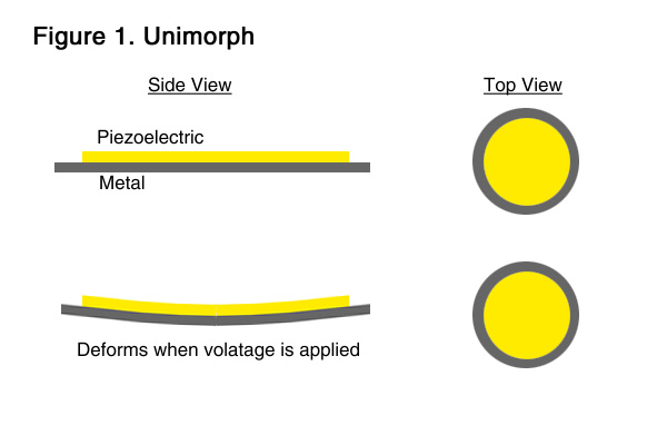 One amplification method is the unimorph design shown in
figure 1. When a voltage is applied across the ceramic and metal plate the
unimorph bends. Reversing the voltage bends it in the other direction.
This device relies on the d31 piezoelectric factor. This is
the change in strain induced perpendicular to the electric field. The factor
d31 is typically half of d33, the induced normal
to the electric field. However, a motion of 0.875 inches can be produced
by a unimorph approximately one inch in diameter and 0.02 inch thick. This
design is typically found in loud speakers.
One amplification method is the unimorph design shown in
figure 1. When a voltage is applied across the ceramic and metal plate the
unimorph bends. Reversing the voltage bends it in the other direction.
This device relies on the d31 piezoelectric factor. This is
the change in strain induced perpendicular to the electric field. The factor
d31 is typically half of d33, the induced normal
to the electric field. However, a motion of 0.875 inches can be produced
by a unimorph approximately one inch in diameter and 0.02 inch thick. This
design is typically found in loud speakers.
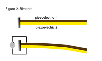
Bimorph
Like the unimorph, the bimorph uses d31 piezoelectric actuation. The bimorph
uses two piezoelectric plates that amplify the deflection as shown in
figure 2.
The two plates can be electrically connected in parallel or in series.
A parallel connection produces twice the displacement as a series connection.
In either case the strain is proportional to the square of the applied
voltage.
RAINBOW
RAINBOWs or Reduced And Internally
Biased Oxide Wafers are piezoelectric wafers with
an additional heat treatment step to increase their mechanical displacements.
In the RAINBOW process, developed by Gene Heartling at Clemson University,
typical PZT wafers are lapped, placed a on graphite
block, and heated in a furnace at 975 C for 1 hour.8 The heating
process causes one side of the wafer to become chemically reduced. This
reduced layer, approximately 1/3 of the wafer thickness, causes the wafer
to have internal strains that shape the once flat wafer into a dome.
The internal strains cause the material to have higher displacements and
higher mechanical strength than a typical PZT wafer. RAINBOWs with
3 mm of displacements and 10 kg point loads have been reported.9
Flextensional Amplifiers
Stacks
 Similar to the bimorph is the piezoelectric stack where
several elements are placed on top of each other and electrically connected
in parallel. The advantage of this design is that a stack uses the d33
which is larger than the d31 effect. Furthermore, displacements are N (number
of elements in stack) greater for the same applied voltage.
Similar to the bimorph is the piezoelectric stack where
several elements are placed on top of each other and electrically connected
in parallel. The advantage of this design is that a stack uses the d33
which is larger than the d31 effect. Furthermore, displacements are N (number
of elements in stack) greater for the same applied voltage.
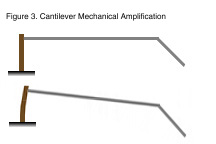
Cantilevers
Other ways of producing mechanical amplification
are through the use of cantilevers in
figure
3. This is just a simple mechanical amplifier that increases
displacement but reduces force.
Inch Worm Motors
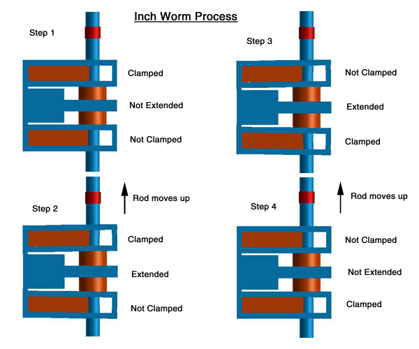
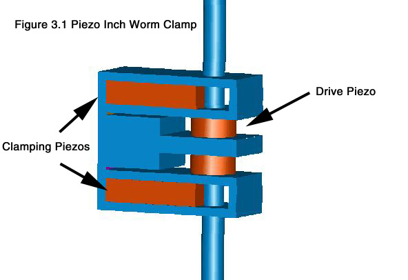 Piezoceramic inch worm motors are linear motors generally used in micro-positioning
applications due to the ability to make very small accurate motions. The
concept is shown in figures 3.1 and 3.2. There are two clamps and one extentional
element. While clamp A is on and clamp B is off the drive piezo is extended.
Then, clamp A is off and B is on returning clamp B to its original position
by relaxing the drive piezo. Again, clamp A is on and clamp B is off the
drive piezo is extended and so on. This is done many times and the rod
moves up. Reversing the clamping sequence can make the rod move down. These
devices can be operated at high frequencies to achieve millimeter per second
motions. Some challenges of inch worm devices are achieving high precision
in manufacturing so that the clamps work properly.
Piezoceramic inch worm motors are linear motors generally used in micro-positioning
applications due to the ability to make very small accurate motions. The
concept is shown in figures 3.1 and 3.2. There are two clamps and one extentional
element. While clamp A is on and clamp B is off the drive piezo is extended.
Then, clamp A is off and B is on returning clamp B to its original position
by relaxing the drive piezo. Again, clamp A is on and clamp B is off the
drive piezo is extended and so on. This is done many times and the rod
moves up. Reversing the clamping sequence can make the rod move down. These
devices can be operated at high frequencies to achieve millimeter per second
motions. Some challenges of inch worm devices are achieving high precision
in manufacturing so that the clamps work properly.
Piezoelectric Rotary Motors
Piezoelectric rotary motors have been developed
that not only weigh much less than conventional electromagnetic motors
but also supply much higher stall torque. Timothy S. Glenn and Nesbit W.
Hagood at MIT have developed an 330 gram ultrasonic piezoelectric motor
that can supply 170 N-cm. of torque1. A 8 mm, 0.26 gram
motor has also been developed that can provide 0.054 N-cm of torque2.
Piezoelectric rotary motors are also available commercially from Shinsei
and Canon. Like other piezoelectric devices, these motors require a high
voltage supply (~150 V).
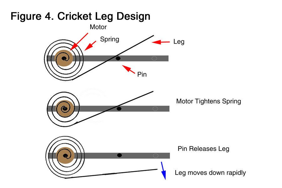
One possible actuator design with a piezoelectric
rotary motor is shown in figure
4. The motor winds a spring up. The other end of the spring is held
by a pin. When the pin is pulled back the leg moves down quickly and produces
a "cricket" jumping motion.
Relaxor-ferroelectrics
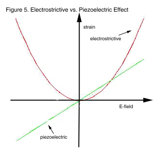 Relaxor-ferroelectrics are similar to piezoelectrics except the strain is
produced by the second order electrostrictive effect as opposed to the first
order effect. The advantages of these actuators over conventional piezoelectrics
include improved stroke (quadratic relationship to applied electric field
shown in figure
5), low hysterisis, return to zero displacement when voltage is suddenly
removed, and insusceptibility to stress depoling3. However,
they have a higher temperature dependence of 65% change in expansion 0-50
C (only 5% for piezos)4.
Relaxor-ferroelectrics are similar to piezoelectrics except the strain is
produced by the second order electrostrictive effect as opposed to the first
order effect. The advantages of these actuators over conventional piezoelectrics
include improved stroke (quadratic relationship to applied electric field
shown in figure
5), low hysterisis, return to zero displacement when voltage is suddenly
removed, and insusceptibility to stress depoling3. However,
they have a higher temperature dependence of 65% change in expansion 0-50
C (only 5% for piezos)4.
All insulators are electrostrictive and
produce a strain under an applied electric field. While this effect is
negligible in most materials, the PMN-PT-BT relaxor-ferroelectric manufactured
by Lockheed Missiles and Space Company had a 0.1% strain at 1 kV/mm.
Magnetostrictive Actuators
Like the Piezoelectric effect where the material deforms
under an applied electric filed, a magnetostrictive material deforms in
a magnetic field. Induced strains and maximum stresses are on the same
order of magnitude as piezoelectrics. One common magnetostrictive material
TERFENOL (TER (Terbium) FE (Iron) NOL Naval Ordinance Laboratory)) produces
a 0.2% strain in a 100 kA/m field5. One major disadvantage of
magnetostrictive actuators is the need for a device to produce the magnetic
fields. This device is typically a coil wrapped around the material. This
makes the device bulky and losses in the coils can be high.
Hybrid Actuators
Because piezoelectrics are capacitive and magnetstricters
are inductive, delivering high electrical power to them individually can
be inefficient and/or require matching networks. Even with with matching
networks, high efficiency over a wide frequency range is difficult. However,
recent work has been done using the two devices together in order to increase
frequency operation6.
Enhanced Electrostrictive Actuators
CRESCENT (CERAMBOW)
THUNDER
Caterpillar d33 unimorph
Ion Exchange Actuators
The theory behind ion-exchange-membrane-metal composites
is fairly complex. Essentially the materials are made of ionizable molecules
that can dissociate and attain a net charge when a electric field is applied.
These actuators have a large deformation in the presence of low applied
voltage. Actuators made from these materials can deform as much as 2.5
cm under a 7 V applied voltage7 . These actuators best
work in a humid environment, but may be encapsulated.
Shape Memory Alloys
Shape memory alloys are metals that deform when electric
current is passed through them. The deformation is due to thermal expansion.
References
1. Timothy S. Glenn, and Nesbit W. Hagood, "Development of a two sided
piezoelectric rotary ultrasonic motor for high torque", SPIE Conference
Procedings Vol. 3041, pp.326-338, 1997.
2. A. M. Flynn, Piezoelectric Ultrasonic Micromotors, MIT PhD.
Thesis, Thesis in Electrical Engineering and Computer Science, June 1995.
3. Craing L. Horn and Natarajan Shankar, "Modeling the Dynamic Behavior
of Electrostrictive Actuators", SPIE Conference Procedings Vol.
3041, pp.268-280, 1997.
4. "Basis of Piezoelectric Positioning", Products for Microposionting
Catalog, Physik Instrumente Co., 1995.
5. Ian W. Hunter and Serge Lafontaine, "A Comparison of Muscle with
Artificial Actuators", IEEE ?, pp.178-185, 1992.
6. Bernd Clephas and Hartmut Janocha, "New linear motor with hybrid
actuator", SPIE Conference Procedings Vol. 3041, pp.316-325.
7. Karim Salehpoor, Mohsen Shahinpoor, and Mehran Mojarrad, "Linear
and Platform Type Robotic Actuators Made From Ion-Exchange Membrane-Metal
Composites", SPIE Conference Procedings Vol. 3040, pp.192-198, 1997.
8. E. Furman, G. Li, and G.H. Heartling, "Electromechanical Properties
of Rainbow Devices", Proceedings of the 9th International Meeting on
Applications of Ferroelectrics, pp.313-318, University Park, PA, 1994.
9. G. H. Haertling, "Chemically Reduced PLZT Ceramics for Ultra-High
Displacement Actuators", Ferroelectrics, vol. 154, pp.233-247, 1990.
 For more information on MEMS research at North Carolina State University
visit the Electronics
Research Laboratory.
For more information on MEMS research at North Carolina State University
visit the Electronics
Research Laboratory.
Actuation for Mobile Micro-Robotics / John
C. Tucker / jctucker@eos.ncsu.edu


 One amplification method is the unimorph design shown in
figure 1. When a voltage is applied across the ceramic and metal plate the
unimorph bends. Reversing the voltage bends it in the other direction.
This device relies on the d31 piezoelectric factor. This is
the change in strain induced perpendicular to the electric field. The factor
d31 is typically half of d33, the induced normal
to the electric field. However, a motion of 0.875 inches can be produced
by a unimorph approximately one inch in diameter and 0.02 inch thick. This
design is typically found in loud speakers.
One amplification method is the unimorph design shown in
figure 1. When a voltage is applied across the ceramic and metal plate the
unimorph bends. Reversing the voltage bends it in the other direction.
This device relies on the d31 piezoelectric factor. This is
the change in strain induced perpendicular to the electric field. The factor
d31 is typically half of d33, the induced normal
to the electric field. However, a motion of 0.875 inches can be produced
by a unimorph approximately one inch in diameter and 0.02 inch thick. This
design is typically found in loud speakers.
 Similar to the bimorph is the piezoelectric stack where
several elements are placed on top of each other and electrically connected
in parallel. The advantage of this design is that a stack uses the d33
which is larger than the d31 effect. Furthermore, displacements are N (number
of elements in stack) greater for the same applied voltage.
Similar to the bimorph is the piezoelectric stack where
several elements are placed on top of each other and electrically connected
in parallel. The advantage of this design is that a stack uses the d33
which is larger than the d31 effect. Furthermore, displacements are N (number
of elements in stack) greater for the same applied voltage.

 Piezoceramic inch worm motors are linear motors generally used in micro-positioning
applications due to the ability to make very small accurate motions. The
concept is shown in figures 3.1 and 3.2. There are two clamps and one extentional
element. While clamp A is on and clamp B is off the drive piezo is extended.
Then, clamp A is off and B is on returning clamp B to its original position
by relaxing the drive piezo. Again, clamp A is on and clamp B is off the
drive piezo is extended and so on. This is done many times and the rod
moves up. Reversing the clamping sequence can make the rod move down. These
devices can be operated at high frequencies to achieve millimeter per second
motions. Some challenges of inch worm devices are achieving high precision
in manufacturing so that the clamps work properly.
Piezoceramic inch worm motors are linear motors generally used in micro-positioning
applications due to the ability to make very small accurate motions. The
concept is shown in figures 3.1 and 3.2. There are two clamps and one extentional
element. While clamp A is on and clamp B is off the drive piezo is extended.
Then, clamp A is off and B is on returning clamp B to its original position
by relaxing the drive piezo. Again, clamp A is on and clamp B is off the
drive piezo is extended and so on. This is done many times and the rod
moves up. Reversing the clamping sequence can make the rod move down. These
devices can be operated at high frequencies to achieve millimeter per second
motions. Some challenges of inch worm devices are achieving high precision
in manufacturing so that the clamps work properly.

 Relaxor-ferroelectrics are similar to piezoelectrics except the strain is
produced by the second order electrostrictive effect as opposed to the first
order effect. The advantages of these actuators over conventional piezoelectrics
include improved stroke (quadratic relationship to applied electric field
shown in figure
5), low hysterisis, return to zero displacement when voltage is suddenly
removed, and insusceptibility to stress depoling3. However,
they have a higher temperature dependence of 65% change in expansion 0-50
C (only 5% for piezos)4.
Relaxor-ferroelectrics are similar to piezoelectrics except the strain is
produced by the second order electrostrictive effect as opposed to the first
order effect. The advantages of these actuators over conventional piezoelectrics
include improved stroke (quadratic relationship to applied electric field
shown in figure
5), low hysterisis, return to zero displacement when voltage is suddenly
removed, and insusceptibility to stress depoling3. However,
they have a higher temperature dependence of 65% change in expansion 0-50
C (only 5% for piezos)4.