ERL MEMS Optical Interconnect Elements
Optical Alignment Grating
The optical alignment gratings were designed mainly for testing purposes,
but can used to passively align optical components, substrate, or packaging
to a MEMS chip such as this one. The one on HC2 includes a flat metal
surface 1mm in diameter to match our expected laser beam size. And on
each side of this surface is a grating of unique frequency, to aid us in
both beam size and alignment. On HC1 it can be seen only as a long
rectangular area in the center of the chip.
Reconfigurable Grating
 This reconfigurable diffraction array is composed of piston-like elements
that are vertically actuated via electrostatic forces. Each piston has
two possible states: up (natural), and down (activated). Together, this
array of 6400 67um by 67um elements approximates a binary reflective-mode
holographic optical element (HOE). Because of the limited number of
layers in this process, there are a few shortcomings in the design:
- The size of the individual elements is larger than desired, to
accommodate addressing lines
- The piston addressing capability is limited to strictly horizontal
and vertical addressing lines; to address a piston, actuating
voltage must be applied to both a horizontal and a vertical
addressing line corresponding to its position in the array.
- Since we will not be creating complex HOE's with this test structure,
there was no need to fully connect the array. Consequently, we
have arranged the pads to actuate patterns of 8 by 8 pistons.
Other diffraction arrays that we have designed contain elements that also
float freely or rock back and forth. A couple of the arrays contain some
bistability, and element sizes ranging from 20um to 80um.
Rotating Grating
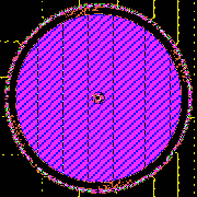
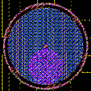
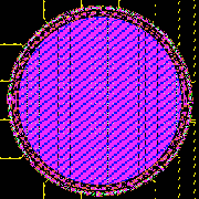 These movable diffraction gratings on this chip are mounted to on horizontally
rotating micromachines. These MEMS devices rotate the surface in 7deg,
11deg, or 30deg increments, as well as sub-degree increments (on a
wobble-motor), to do one of the following:
- Rotate the orders of a diffraction pattern about the chip surface normal
- Horizontally move the focal point of a Fresnel approximation
Realignable Mirrors
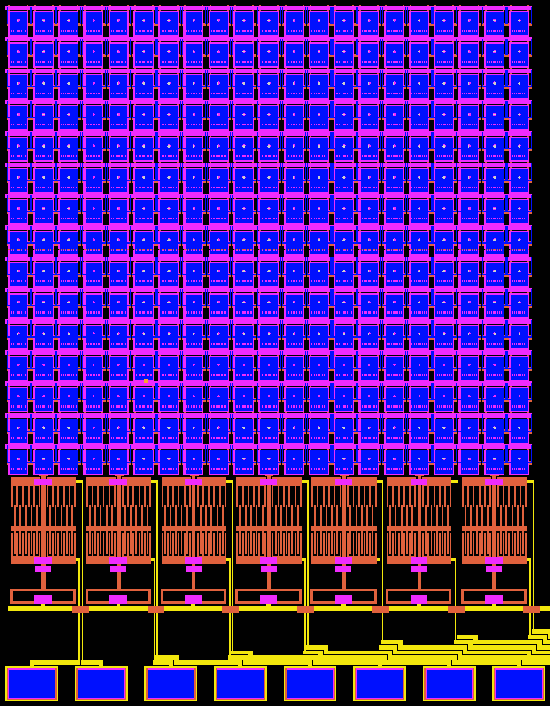 This re-alignable mirror array consists of 315 72um by 90um reflective
elements that can be pushed vertically, out of the chip surface plane.
These elements are pushed out via electrostatically actuated
comb-motors
attached to columns of these elements. Consequently, a fine pitch adjustment
should be available at high reflection angles to the chip surface normal.
Click
here to return to the ERL Homepage.
David Winick,
Emmanuel Maitre, Mouna Nakkar,
and Paul Franzon
 This reconfigurable diffraction array is composed of piston-like elements
that are vertically actuated via electrostatic forces. Each piston has
two possible states: up (natural), and down (activated). Together, this
array of 6400 67um by 67um elements approximates a binary reflective-mode
holographic optical element (HOE). Because of the limited number of
layers in this process, there are a few shortcomings in the design:


 These movable diffraction gratings on this chip are mounted to on horizontally
rotating micromachines. These MEMS devices rotate the surface in 7deg,
11deg, or 30deg increments, as well as sub-degree increments (on a
wobble-motor), to do one of the following:
